SIZING AND SELECTION SAFETY COUPLINGS SK l SL l ES
Symbols
| TKN | Rated torque of the coupling (Nm) |
| TAN | Load torque (Nm) |
| TAS | Peak torque of the motor (Nm) |
| JL | Moment of the inertia of the load (kgm²) |
| JA | Moment of the inertia of the drive (kgm²) |
| PAN | Drive power (kW) |
| ∝ | Angular acceleration |
| t | Acceleration / deceleration time (s) 1/s2 |
| ω | Angular velocity (1/s) |
| n | Drive speed (min -1) |
| s | Screw lead (mm) |
| Fv | Feed force (N) |
| η | Spindle efficiency |
| d0 | pinion dia. (pulley) (mm) |
| CT | Torsional stiffness of the coupling (Nm/rad) |
| JMasch. | Total load inertia (kgm²) (e.g. spindle + slide + workpiece + 1/2 of coupling) |
| JMot. | Total driving inertia (kgm²) (motor including gear ratio + 1/2 of coupling) |
| fe | Natural frequency of the two mass system (Hz) |
φ
| Torsional deflection (degree)
|
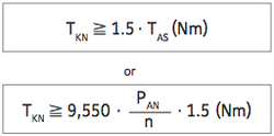
According to disengagement torque
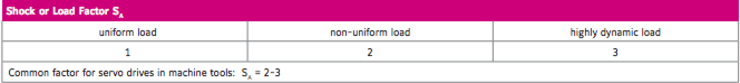
Torque limiters are generally selected according to the required disengagement torque, which must be greater than the torque required for regular operation. The disengagement of the torque limiter is most commonly determined in accordance with the drive data. For this purpose, the following calculation applies:
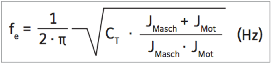
According to resonant frequency (SK2 / SK3 / SK5 with metal bellows ES2 / ESL with elastomer ring)
The torsional natural frequency of the coupling must be significantly higher or lower than that of the equipment. For the mechanical substitution model the two mass system applies:
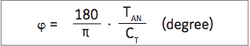
According to torsional deflection (SK2 / SK3 / SK5 with metal bellows - ES2 / ESL with elastomer ring)
To calculate transmission error as a result of torsional stress:
According to load holding function system
Load Holding Version
The SK1, SKP, and SKN models in the load holding version can secure a minimum of 2x their torque setting after disengagement. The SK2, SK3, and SK5 models can secure only up to the torque rating oft he flexible bellows after disengagement.