SIZING AND SELECTION DRIVE SHAFT COUPLINGS
Symbols
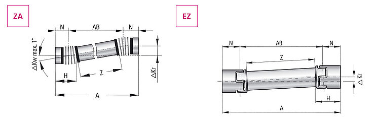
| A | Overall length (mm) |
| AB | Distance between flextures (mm) AB = (A – 2xN) |
| Z | Tube length (mm) Z = (A – 2xH) |
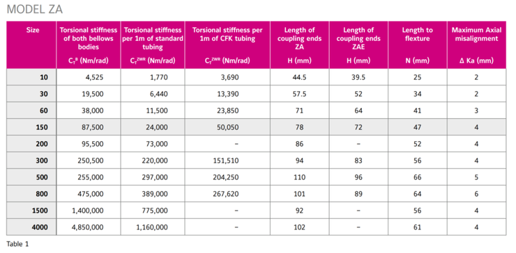
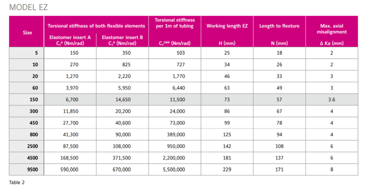
| H | Length of coupling ends (mm) |
| N | Length to flexture (mm) |
| TAS | Peak torque of the drive (Nm) |
| φ | Torsional deflection (degree) |
| CTB | Torsional stiffness of both flexible elements (Nm/rad) |
| CTZWR | Torsional stiffness per 1m of tubing (Nm/rad) |
| CTZA | Total torsional stiffness (Nm/rad) |
| nk | Critical speed (1/min.) |
| CTdynE | Dynamic torsional stiffness of both elastomer inserts (Nm/rad) |
| CTdynEZ | Total torsional stiffness (Nm/rad) |
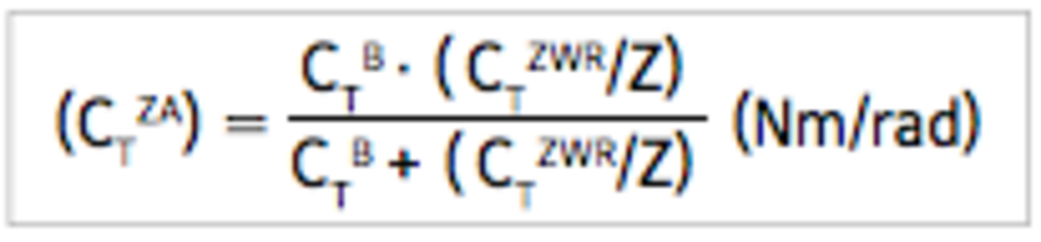

According to torsional stiffness
Condition: Line shaft ZA, size 1.500 TAS = 1.500 Nm
Wanted: Total torsion stiffness CTZA
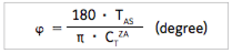
According to torsional deflection
Condition: Line shaft ZA, size 1.500 TAS = 1.500 Nm
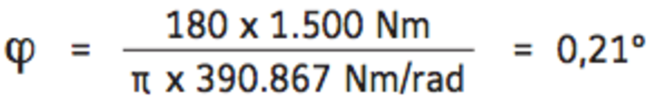
Wanted: Torsional deflection at maximum acceleration torque TAS
Measurement (A) of the line shaft = 1,5 m
Length (Z) of tubing = A - (2xH) = 1,344 m
With a maximum torque of 1.500 Nm the torsional deflection is 0,21°.
R+W Calculation Program
Using proprietary software, R+W will calculate the specific mechanical details of exactly the model you plan to use. Overall length, tube materials (e.g. steel, aluminum, CFK), and other factors are used to determine a number of performance values unique to your line shaft coupling.
| Critical Speed | nk | 1/min. |
| Torsional stiffness of tubing | CTZWR | Nm/rad |
| Overall stiffness | CTZA | Nm/rad |
| Torsional deflection | φ | Grad-Min-Sec |
| Total weight | m | kg |
| Moment of inertia | J | kgm2 |
| Maximum misalignment | ΔKr | mm |